American Flyer #322 SIT: Restoration #1
*I am constantly updating this page so please check back often.
Last Updated: 3/28/2022
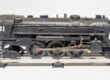
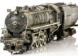
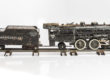
Welcome to my first in a series of blog posts that will follow the restoration of various relic toy trains. In this inaugural kickoff, I will tackle the American Flyer #322 smoke in tender (SIT) Hudson locomotive with a timestamp in the boiler shell of 1947. This engine was a local Long Island find that came bundled with some other engines and rolling stock (future restorations). My goal with this #322 will be to bring it back to its original chugging glory. Spoiler…it doesn’t chug now.

The 1947 date stamp on the inside of the boiler.
The first step is to release the tender and remove the rear truck from the engine. First, unscrew the rear truck stud (PA4938) to release the rear truck assembly (XA10002) from the engine. The tender is connected to the engine by three components; the couple, two wires, and the rubber smoke tube. It is a good idea to undo the wires and smoke tube first to prevent any accidents from undoing the tender coupler. This can simply be done by pulling the two wire contacts from the Jack Panel (XA10662) on the back of the engine. The smoke tube can be pulled from the smoke tube on the front of the tender. This may vary in difficulty based on the build up of hardened smoke fluid and the dry rot of the rubber smoke tube. Finally, remove the coupler stud (PA4939) which releases the tender coupler (PA10244). The #322 locomotive is now disconnected from the tender.


Unscrew the rear truck, pull the two wires from the jack panel, pull the rubber hose from the smoke tube on the back of the tender, and disconnect the tender coupler to separate the boiler from the tender.
Now that the boiler is separated from the tender, let’s work on disassembling it. First, take apart that spider web of linkages that makes those wheels spin. Using a small flat-headed screwdriver, unscrew the three screws (PA9288, PA10598 x2) that attach the crosshead (PA10595) and eccentric crank (XA10447) assembly to the boiler. As I was working on this article, I realized that this engine has the incorrect linkage screws. The linkage screws are all PA9288 screws which are a shouldered version. There should be four (two on each side) PA10598 link studs on the furthest back holes on the boiler chassis. These studs are non-shouldered.

The correct part numbers for the linkage screws. Note that the two rearmost screws are PA9288’s, they are incorrect and should be PA10598 studs.
Once the linkages are free from the boiler, free them from the wheels. Using a 1/4” wrench, undo the side rod stud (PA5447) and be careful not to lose the spacer (PA7237) between the crosshead assembly and side rod. This stud will free the two linkages from the boiler and wheels, leaving the side rod (PA9280) connecting the wheels attached by two screws. Use a 3/16” inch nut driver to undo the two smaller side rod studs (PA7421) and remove the side rod from the wheels. Repeat this whole process on the other side. Once the linkages are removed, there will be a total of 20 pieces.


First, unscrew the three screws and 1/4″ stud to release the crosshead and eccentric crank assembly. Second, remove the two studs from the side rod to release it from the wheels.
LINKAGES AND SIDE ROD PARTS

|
Part |
Part Number |
Quantity |
Description |
|---|---|---|---|
| 1 | PA7421 | 4 | Side Rod Screw |
| 2 | PA9288 | 2 | Crosshead Screw |
| 3 | PA10598 | 4 | Link Stud |
| 4 | PA5447 | 2 | 1/4″ Side Rod Stud |
| 5 | PA9280 | 2 | Side Rod |
| 6 | XA10597 | 2 | Crosshead Assembly |
| 7 | PA7237 | 2 | Spacer for Piston Rod |
| 8 | XA10447 | 2 | Eccentric Crank Assembly |
The nice thing about the #322 with the smoke unit in the tender is that there is no light bulb bracket attached to the front boiler frame. This means no soldering is required to remove the boiler assembly, instead, it can just be pulled loose. It’s a good idea to remove the jack panel at the rear of the engine now to prevent any pulling of wires once the chassis is set free. This is simply done by unscrewing the two screws (S230-B) that hold the 2-wire jackpanel (XA10287) to the frame.

Remove the boiler front assembly and light bulb bracket to separate the wheel chassis from the boiler body.

To remove the 2-wire jack panel (XA10662) from the boiler frame of the American Flyer #322 SIT, remove the two screws (S230-B).
Now, let’s get the boiler frame off the chassis. Flip the engine upside down, preferably on some sort of foam pad. This is a great time to use all that wasted Amazon packaging. Move the front truck (XA10012) to the side to reveal the front pilot screw (S16). Be careful not to lose the lock washer (PA3769) under the screw. Notice my engine is missing the lock washer. Add it to the replace list. With the screw removed, carefully lift the pilot (PA9245) from the chassis. Be careful of the long handrails that terminate in the pilot. Gently wiggle them free of the truck. With the front truck removed you will now gain access to the screw (S47) holding the steam chest (PA10056) and crosshead guides (PA10595). Like the previous screw, be careful not to lose the lock washer. Finally, the last two visible screws (S14) will release the wheeled chassis from the boiler frame. As always, don’t lose the lock washers (PA3769)!


In order to separate the chassis from the boiler frame start by removing the front pilot, steam chest, and finally the two screws holding the wheeled chassis to the boiler frame.
Now, let’s get those wheels free. Don’t do what I did and leave the light bulb in. Remove it to prevent the breakage of this expensive little bulb. The chassis is being held on to the frame by a channel directly above the rear drive wheel on the chassis. By simply sliding the chassis rearward towards the cab, the chassis will be free. With a little wiggling, you will be able to separate the two pieces.

The portion of the chassis frame that holds tight to the boiler frame.

Removing the chassis from the boiler frame.
With the boiler body separated, there are a couple of odds and ends to take care of before we move to disassembling the inner workings. The cylinder and steamchest (PA10056) still have the crosshead guides (PA10595) attached by two screws along with their lock washers (PA3769). Remove these screws to free the crosshead guides from the cylinder and steamchest. Since the handrails are in need of a good polish they are to be removed as well. Using small pliers, straighten out the ends of the cotter pins (PA8923) holding the handrails to the boiler body.

Remove the two screws and lock washers from the steamchest to free the crosshead guides.

Using small pliers, straighten out the ends of the cotter pins holding the handrails to the boiler body.
Before doing any of the following steps, undo the solder holding the wires to the headlight assembly. I forgot to do this. It makes it much more difficult once the reverse unit and brush bracket are loose. To free the reverse unit, start by removing the two screws at the rear of the frame. Note that this engine may not have the correct fasteners holding the reverse unit. The part diagram calls these two “screws” a tubular rivet. Any help on these two parts would be greatly appreciated, leave a comment down below.

The inner workings of the motor and reverse unit within the boiler.
Regardless of the “screw” type, make sure not to lose the insulator bushing between the reverse unit and wheel chassis. This insulator prevents the system from shorting out.

Remove the two screws at the back of the reverse unit to free it from the wheeled chassis.
With the reverse unit free, the brush bracket screws (S-295) are the last things holding the field (XA9547) and brush bracket assembly (XA9565-A) to the chassis. Be wary while removing the brush bracket assembly, the slotted brushes (PA9603) that sit in the brush tubes are under tension by the brush springs (PA9566). If not careful the brushes could shoot into the atmosphere, never to be seen again. Also, be on the lookout for a thrust washer on the armature worm gear shaft.


Remove the two screws holding the brush bracket assembly to the chassis. Be careful not to lose the brushes that are held under tension by the brush springs. Also, make note if the armature has a thrust washer that could be on either the front armature shaft or on the back of the armature on the worm gear shaft.
Check back often for updates!
Last Updated: 3/28/2022
American Flyer #322 SIT: Restoration #1
*I am constantly updating this page so please check back often.
Last Updated: 3/28/2022

Welcome to my first in a series of blog posts that will follow the restoration of various relic toy trains. In this inaugural kickoff, I will tackle the American Flyer #322 smoke in tender (SIT) Hudson locomotive with a timestamp in the boiler shell of 1947. This engine was a local Long Island find that came bundled with some other engines and rolling stock (future restorations). My goal with this #322 will be to bring it back to its original chugging glory. Spoiler…it doesn’t chug now.

The 1947 date stamp on the inside of the boiler.
The first step is to release the tender and remove the rear truck from the engine. First, unscrew the rear truck stud (PA4938) to release the rear truck assembly (XA10002) from the engine. The tender is connected to the engine by three components; the couple, two wires, and the rubber smoke tube. It is a good idea to undo the wires and smoke tube first to prevent any accidents from undoing the tender coupler. This can simply be done by pulling the two wire contacts from the Jack Panel (XA10662) on the back of the engine. The smoke tube can be pulled from the smoke tube on the front of the tender. This may vary in difficulty based on the build up of hardened smoke fluid and the dry rot of the rubber smoke tube. Finally, remove the coupler stud (PA4939) which releases the tender coupler (PA10244). The #322 locomotive is now disconnected from the tender.

Unscrew the rear truck stud (PA4938) to release the rear truck assembly (XA10002) from the engine.

The tender is connected to the engine by three components; the couple, two wires, and the rubber smoke tube.

Remove the coupler stud (PA4939) which releases the tender coupler (PA10244).
Now that the boiler is separated from the tender, let’s work on disassembling it. First, take apart that spider web of linkages that makes those wheels spin. Using a small flat-headed screwdriver, unscrew the three screws (PA9288, PA10598 x2) that attach the crosshead (PA10595) and eccentric crank (XA10447) assembly to the boiler. As I was working on this article, I realized that this engine has the incorrect linkage screws. The linkage screws are all PA9288 screws which are a shouldered version. There should be four (two on each side) PA10598 link studs on the furthest back holes on the boiler chassis. These studs are non-shouldered.

The correct part numbers for the linkage screws. Note that the two rearmost screws are PA9288’s, they are incorrect and should be PA10598 studs.
Once the linkages are free from the boiler, free them from the wheels. Using a 1/4” wrench, undo the side rod stud (PA5447) and be careful not to lose the spacer (PA7237) between the crosshead assembly and side rod. This stud will free the two linkages from the boiler and wheels, leaving the side rod (PA9280) connecting the wheels attached by two screws. Use a 3/16” inch nut driver to undo the two smaller side rod studs (PA7421) and remove the side rod from the wheels. Repeat this whole process on the other side. Once the linkages are removed, there will be a total of 20 pieces.

Removing the screws to release the crosshead and eccentric crank assembly.

Removing the stud to release the crosshead and eccentric crank assembly.

Removing the stud (PA7421) to release the side rod (PA9280).
LINKAGES AND SIDE ROD PARTS

|
Part |
Part Number |
Quantity |
Description |
|---|---|---|---|
| 1 | PA7421 | 4 | Side Rod Screw |
| 2 | PA9288 | 2 | Crosshead Screw |
| 3 | PA10598 | 4 | Link Stud |
| 4 | PA5447 | 2 | 1/4″ Side Rod Stud |
| 5 | PA9280 | 2 | Side Rod |
| 6 | XA10597 | 2 | Crosshead Assembly |
| 7 | PA7237 | 2 | Spacer for Piston Rod |
| 8 | XA10447 | 2 | Eccentric Crank Assembly |
The nice thing about the #322 with the smoke unit in the tender is that there is no light bulb bracket attached to the front boiler frame. This means no soldering is required to remove the boiler assembly, instead, it can just be pulled loose. It’s a good idea to remove the jack panel at the rear of the engine now to prevent any pulling of wires once the chassis is set free. This is simply done by unscrewing the two screws (S230-B) that hold the 2-wire jackpanel (XA10287) to the frame.

Remove the boiler front assembly and light bulb bracket to separate the wheel chassis from the boiler body.

To remove the 2-wire jack panel (XA10662) from the boiler frame of the American Flyer #322 SIT, remove the two screws (S230-B).
Now, let’s get the boiler frame off the chassis. Flip the engine upside down, preferably on some sort of foam pad. This is a great time to use all that wasted Amazon packaging. Move the front truck (XA10012) to the side to reveal the front pilot screw (S16). Be careful not to lose the lock washer (PA3769) under the screw. Notice my engine is missing the lock washer. Add it to the replace list. With the screw removed, carefully lift the pilot (PA9245) from the chassis. Be careful of the long handrails that terminate in the pilot. Gently wiggle them free of the truck. With the front truck removed you will now gain access to the screw (S47) holding the steam chest (PA10056) and crosshead guides (PA10595). Like the previous screw, be careful not to lose the lock washer. Finally, the last two visible screws (S14) will release the wheeled chassis from the boiler frame. As always, don’t lose the lock washers (PA3769)!


In order to separate the chassis from the boiler frame start by removing the front pilot, steam chest, and finally the two screws holding the wheeled chassis to the boiler frame.
Now, let’s get those wheels free. Don’t do what I did and leave the light bulb in. Remove it to prevent the breakage of this expensive little bulb. The chassis is being held on to the frame by a channel directly above the rear drive wheel on the chassis. By simply sliding the chassis rearward towards the cab, the chassis will be free. With a little wiggling, you will be able to separate the two pieces.

The portion of the chassis frame that holds tight to the boiler frame.

Removing the chassis from the boiler frame.
With the boiler body separated, there are a couple of odds and ends to take care of before we move to disassembling the inner workings. The cylinder and steamchest (PA10056) still have the crosshead guides (PA10595) attached by two screws along with their lock washers (PA3769). Remove these screws to free the crosshead guides from the cylinder and steamchest. Since the handrails are in need of a good polish they are to be removed as well. Using small pliers, straighten out the ends of the cotter pins (PA8923) holding the handrails to the boiler body.

Remove the two screws and lock washers from the steamchest to free the crosshead guides.

Using small pliers, straighten out the ends of the cotter pins holding the handrails to the boiler body.
Before doing any of the following steps, undo the solder holding the wires to the headlight assembly. I forgot to do this. It makes it much more difficult once the reverse unit and brush bracket are loose. To free the reverse unit, start by removing the two screws at the rear of the frame. Note that this engine may not have the correct fasteners holding the reverse unit. The part diagram calls these two “screws” a tubular rivet. Any help on these two parts would be greatly appreciated, leave a comment down below.

The inner workings of the motor and reverse unit within the boiler.
Regardless of the “screw” type, make sure not to lose the insulator bushing between the reverse unit and wheel chassis. This insulator prevents the system from shorting out.

Remove the two screws at the back of the reverse unit to free it from the wheeled chassis.
With the reverse unit free, the brush bracket screws (S-295) are the last things holding the field (XA9547) and brush bracket assembly (XA9565-A) to the chassis. Be wary while removing the brush bracket assembly, the slotted brushes (PA9603) that sit in the brush tubes are under tension by the brush springs (PA9566). If not careful the brushes could shoot into the atmosphere, never to be seen again. Also, be on the lookout for a thrust washer on the armature worm gear shaft.


Remove the two screws holding the brush bracket assembly to the chassis. Be careful not to lose the brushes that are held under tension by the brush springs. Also, make note if the armature has a thrust washer that could be on either the front armature shaft or on the back of the armature on the worm gear shaft.
Check back often for updates!
Last Updated: 3/28/2022
Thank you, very informative
Thanks for taking the time to check it out!
Awesome guide, and very timely. I am in the process of rebuilding two 322s with smoke in tender, a 1946 and a 1947.
Great photos and format. A couple of things to note – early SIT units from the factory used all PA9288’s, latter units with those and 10598s. Secondly I don’t recommend using a thrust washer on the commutator end of an early steam armature that doesn’t have an oil slinger. You risk shorting out the comms with it. A thrust washer (usually 0.020″) on the worm end only. Later production armatures with oil slingers usually benefit from that and a 0.005″ thrust washer on the comm end. Great work again. Thanks for sharing.
Dave, thanks for the insight on the screws. I was getting confused because every 322 I touched had a different configuration.
Ok, don’t leave me hanging! I just purchased a ’47 322 and am ready to do some work. The disassembly piece is great, but where do we go from here? Love your page, you’ve been a great help with all things AF.